10 Steps To Measuring A Wheel
In order to help us get the correct wheel for your machine or application, we need to get the correct information from you about the wheel you require.
Step 1 - Do you have the Original Equipment Manufacturer’s or the wheel manufacturer’s part number for the wheel?
If you have any of those numbers, call our customer service staff to see if we may be able to cross reference the information in the database of part numbers we already have. If we don’t have it in our database already, we will want to add it with the other information collected. If none of these numbers are available, proceed to step 2.
Step 2 - What is the specific tire size you are using?
The tire size will tell us the proper rim diameter and width required. The size of the tire may also help us determine the correct rim profile to use. In certain cases it won’t and we will need you to help us identify the profile from the rims shown in this catalog.
In most cases, steps 1 and 2 will give us the information we need to make sure we are providing you with the correct wheel for your machine.
Step 3 - How many bolt holes are there?
Simply count the number of holes in the disc for the wheel studs. We also need to know if the holes are equally spaced or not. If in doubt, measure the distance between a few of the holes to see.
Step 4 - What is the Bolt Circle size?
How you correctly measure the Bolt Circle depends on how many holes are in the disc. If the disc has an even number of holes and they are equally spaced, the illustration on the right shows you how to measure the dimensions easily

Use a tape measure or a straight edge and measure the holes as shown in the illustration. When measuring the Bolt Circle, you want to measure from the top edge of the hole at one end to the top edge of the hole on the other end. You want to be as exact as possible in your measurements. The following is a listing of standard bolt patterns used in many agricultural wheels. You may find your measurements are one of these patterns. In a few cases, you may have an odd pattern that is not standard.
Odd numbered bolt holes are the only real difficult bolt patterns to measure because they require four separate measurements and a little math. Reference the illustration for the 5 hole patternon the previous page, measure dimension A, B, C and D. Plug those numbers into the formula A+B+C+D = Bolt Circle, and you have the correct dimension for the odd numbered bolt holes.

Note: This only works when the holes are equally spaced. If the bolt holes are grouped (i.e. 2 holes, a space, 2 more holes, a space,) this will require that you send the wheel to one of our facilities to be measured by our technical staff to make sure we have the correct pattern information.
Measure the Inside Diameter (ID) of the Pilot Hole as shown in the illustration on page 7.
Remember that for hubs with flat-based wheel nuts, the Pilot Hole should have a plus tolerance of a few tenths of a millimeters. The Pilot hole should both support the wheel and guide it correctly onto the hub. If the gap between the hub and the disc is too large, the disc will not center on the hub and the vehicle will rock while in motion, greatly increasing the risk of the wheel nuts coming loose.
For applications with tapered or rounded wheel nuts, the plus tolerance of the Pilot Hole can vary between one or two millimeters. Countersinks in the bolt holes should fit the nuts shape correctly, as the nuts are supposed to center the disc. Incorrect countersinks may cause wheel nuts to come loose.
Step 5 - Are the bolt holes chamfered or straight?
If the bolt holes are straight, that means you are using a “flange wheel nut” to secure the wheel to the hub. If the bolt holes have a chamfer, we need to know if it is spherical or conical. We also need to know if the chamfer is only on one side or both.
If the holes are chamfered, you could give us the nut information and we can translate that into the correct chamfer information.
If you don’t have the nut information, you will have to measure the chamfer widths and depths. Reference the illustration on Page 8.
If necessary, you can send us a wheel nut to make sure the measurement is exact.
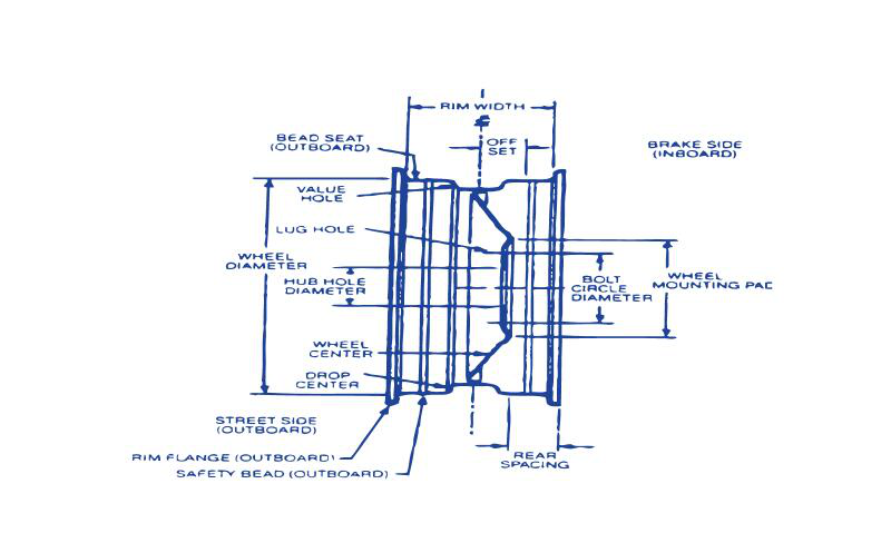
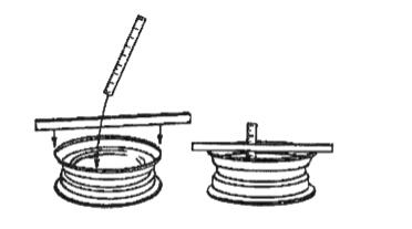
Step 6 - What is the wheel offset?
Take a measurement for the Back Spacing which we will translate into the correct offset for the wheel. Reference the illustration to the right for measuring the back spacing. You need to take the wheel and lay it down so the machine side of the wheel is facing up.
The Back Spacing dimension is the distance from the extreme back edge of the rim, not the bead seat, to the mounting pad of the disc. Lay a straight edge across the back edge of the rim and measure down to the mounting pad. Nearly all custom wheels use this measurement method to indicate the location of the mounting pad in relation to the rim. We can use this dimension to calculate the actual Inset or Outset measurement for the whee
Step 7 - What kind of disc is being used in the wheel?
The disc can be either a flat plate or formed disc. Nearly all agricultural wheels are manufactured with a formed disc. A formed disc is usually pushed into the center of the rim with a press and then welded in place. The disc usually has a leg width greater than the disc thickness. This leg provides greater support and disperses the load stress over a wider area of the rim center than would a flat plate disc welded in the center.
Several of the possible disc profiles are pictured in the illustrations below. Discs can come in several different thicknesses and diameters for the different rim sizes that are used.
You should be able to easily identify the disc type in the wheel you have from the illustrations above. Just let your customer service person know which one you require

Step 8 - Where is the valve hole located in the rim? What kind of valve hole is it? Does it have a valve guard?
One piece rims will have a valve hole which can be located in many different locations in the rim. Depending on the profile and size of the rim, the valve hole could be located in one or two of these locations. Reference the illustrations below.
The small drop center rims shown in the Illustration 1 show the possible locations for 4 different valve holes. H1 shows a valve hole that has been embossed into the rim. H3 shows a valve hole with no embossment and is mechanically punched into the rim.
The 15° rim in Illustration 2 shows four possible locations for a valve hole.
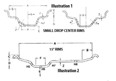
The DW rim in Illustration 3 shows the location for two possible locations for a valve hole. One of those locations shows a valve guard. In the case of the DW rim, nearly all of the rims will come with two valve holes located as displayed in these 3 illustrations.
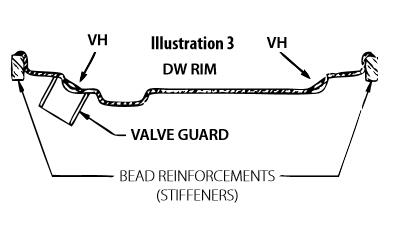
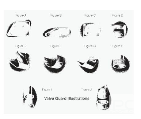
There are various different kinds of valve guards available and in use today. Reference the Valve Guard Illustrations to the right.
Step 9 - Are there any other items on the wheel not already described such as bead reinforcements, etc.?
Bead reinforcements are used in rough duty applications such as forestry or heavy load applications such as grain carts. There are various kinds of bead reinforcements in use other than the ones shown in illustration 3 on the previous page.
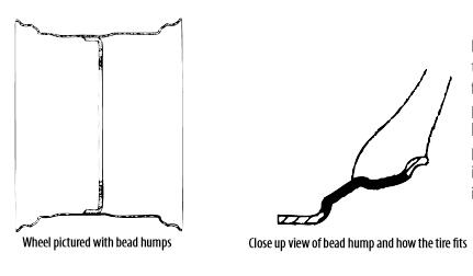
Does your rim have bead humps? Reference the illustration to the left. Bead humps are formed into the rim when it is rolled. The purpose of the bead humps is to lock the tire bead into the bead area of the rim should air pressure run low or if you get a flat. This is intended to keep the tire from easily dislodging itself from the rim bead area.
Step 10 - Determine if you want your wheel primer coated, your desired paint color, and if you want any special rust preventative treatments (such as Ecoat, epoxy primer or zinc oxide).
You have three options for primer and rust/corrosion prevention:
1) Epoxy primer is a standard undercoat that provides a minimum of rust and corrosion prevention.
2) Ecoat provides a medium amount of rust and corrosion prevention (up to 600 hours of salt spray protection).
3) Zinc oxide provides the maximum amount of rust and corrosion prevention (up to 6000 hours of salt spray protection).
The standard paint colors available are white, off-white, yellow, orange, silver or black.